Soluciones Kenko · 7/17/2026
The sensor that decided the World Cup: What is inside the FIFA ball?
Two plays at the 2026 World Cup were decided by the sensor inside the ball. We explain what a MEMS IMU is, why we chose SPI, and how the ST1VAFE6AX fuses accelerometer and gyroscope in its own silicon.
Two plays at the 2026 World Cup ended in the same argument.
In Croatia 1-2 Portugal, the stoppage-time equalizer was disallowed in minute 90+14 for a millimetric offside. VAR detected a minimal touch by Igor Matanović on the incoming cross, a touch no television replay managed to show. Matanović later said he had felt "a slight contact with my hair," and that the referee confirmed to him that the chip in the ball had registered that contact. With that instant as the time reference, Mario Pašalić was in an offside position and Gvardiol's goal never counted.
In England 2-1 Norway, the opposite happened. Norway claimed the ball hit an aerial camera cable during the goal kick that led to Bellingham's equalizer, which by the laws of the game should have stopped play. FIFA replied that the Connected Ball sensor showed no peak in the ball's "heartbeat" while it was in the air, meaning no contact.
In one case the technology says there was contact, and in the other that there was not. It is the same sensor answering the same question, whether something touched the ball and at what moment, and in both cases its answer outweighed what sixty thousand people saw in the stadium.
What the chip in the ball is
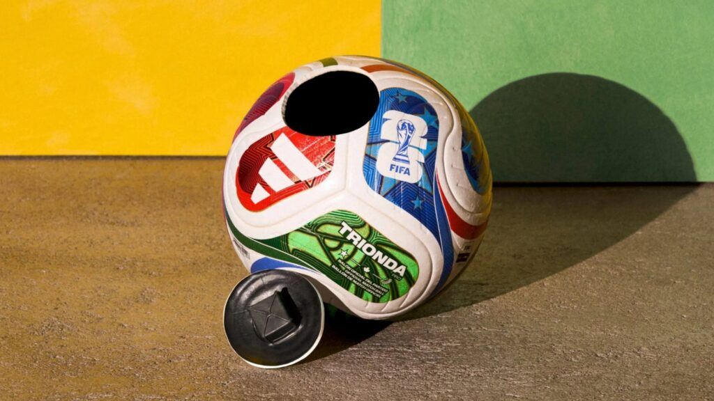
FIFA calls it Connected Ball Technology. The official 2026 World Cup ball, the Adidas Trionda, developed together with Kinexon, carries an IMU sampling at 500 Hz, one measurement every 2 milliseconds. In the Al Rihla at Qatar 2022 the sensor was suspended at the geometric center of the ball; in the Trionda the chip is mounted inside one of the four panels, with counterweights in the other three to keep the flight balanced.
To the sensor, a touch on the ball is an acceleration spike. Sampling at 500 Hz is what allows itto capture that transient and timestamp it with 2 ms resolution; with that, the camera system determines where every player was at that exact instant. The provides the when, and the cameras the where.
What an IMU is
An IMU (Inertial Measurement Unit) measures two things with two different sensors inside the same package.
The accelerometer measures linear acceleration on three axes, that is, how hard and in which direction something is pushed, braked, or struck.
The sensor is a MEMS (Micro-Electro-Mechanical System), a tiny silicon proof mass suspended by silicon springs, etched photolithographically on the same wafer. When the chip accelerates, the mass lags behind due to inertia, and that displacement changes the differential capacitance between interdigitated comb fingers. The readout circuit measures that capacitance change, demodulates it, and digitizes it into a number proportional to the acceleration.
The gyroscope measures angular velocity, in degrees per second (°/s). It is also MEMS, but it relies on the Coriolis effect, inside there is a mass vibrating at a constant frequency along one axis, and if the chip rotates, that mass experiences an apparent force perpendicular to its vibration velocity, proportional to the rotation rate (F = −2m·Ω×v). That force deflects the vibration onto a secondary sense axis, the deflection is measured capacitively just like in the accelerometer, and out comes the °/s.
The ST1VAFE6AX
It is a six-axis IMU from STMicroelectronics, a three-axis accelerometer and a three-axis gyroscope (the latter with a configurable full scale from ±125 up to ±4000 °/s). It also includes a biomedical analog front-end, the vAFE (vertical analog front-end), a single-ended or differential input amplifier with a 50/60 Hz digital notch filter that samples biopotentials at a fixed 240 Hz. That is why the same chip can read an ECG-like signal, something that does not make it into the video but explains why the protocol that appears later has an ECG channel living alongside the IMU one. Rounding it out is an internal 4.5 KB FIFO with compression and dynamic allocation.
Choosing the bus, because the sensor speaks both
The ST1VAFE6AX speaks I2C and SPI (and also MIPI I3C, which we leave out of this comparison), so you have to pick.
| I2C | SPI | |
|---|---|---|
| Wires | 2 (SDA, SCL) | 4 (SCLK, MOSI, MISO, CS) |
| Speed on this chip | 400 kHz (1 MHz in fast-mode+) | Up to 10 MHz |
| Addressing | By slave address | One CS pin per device |
| ACK per byte | Yes | No |
| Clock stretching | The slave can stall the bus | Does not exist |
| Duplex | Half | Full |
We went with SPI for three reasons.
- Bandwidth: we do not read one sample at a time, we drain an entire FIFO in one burst-read transaction, and there the difference between 1 MHz and 10 MHz multiplies across every byte of the block.
- Determinism: I2C has arbitration and clock stretching, meaning the slave can stall the bus by holding SCL low, and when what matters is the exact instant of an event you want a bus where the master owns the clock and nothing can pause itself.
- Protocol overhead: SPI sends no per-byte ACK and no slave addresses, and being full duplex it returns data on MISO while you are still writing the register address on MOSI.
The fusion happens inside the sensor
The ST1VAFE6AX includes SFLP (Sensor Fusion Low Power), a block that fuses accelerometer and gyroscope in its own silicon and directly outputs a rotation quaternion (the game rotation vector) at a configurable rate between 15 and 480 Hz (we use 120 Hz), placed in the same FIFO as the raw samples. Since there is no magnetometer, heading is not referenced to magnetic north, it is orientation relative to startup, with the vertical anchored to gravity, which for characterizing the motion of an object is exactly what you need.
Fusion is necessary because the two sensors fail in complementary ways. The gyroscope is precise in the short term but drifts. To get an angle you have to integrate °/s over time, and every micro-error of bias accumulates in the integral. The accelerometer does not drift, because gravity always points down and serves as an absolute tilt reference, but it is noisy and cannot distinguish gravity from the user's linear acceleration. The fusion uses the gyroscope as the high-band signal, for fast detail, and the accelerometer as the low-band correction, to tie the slow drift back to gravity.
Doing that on the microcontroller costs CPU and, above all, timing. the quality of the integration depends on samples arriving at exact intervals. Doing it in the sensor is nearly free in energy and leaves every sample timestamped inside the FIFO with the chip's own clock, without the jitter of the scheduler or the micro's interrupts.
The FIFO stores the quaternion in 6 bytes instead of the 16 that four 32-bit floats would take. It stores x, y, z as binary16 (IEEE-754 half-precision float: 1 sign bit, 5 exponent bits, and 10 mantissa bits, two bytes each) and omits w entirely, which it can do because it is a unit quaternion and therefore w² + x² + y² + z² = 1. On the other side it is reconstructed with w = √(1 − (x² + y² + z²)), taking the non-negative root, which is how ST defines it.
That quaternion is the object's orientation in space at every sample. With it you can recover full attitude without accumulating the error of integrating the gyroscope by hand.
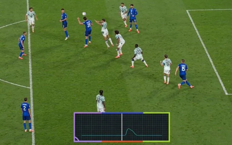
And that is exactly what showed up at the World Cup. The heartbeat FIFA displayed on the broadcasts is this same stream, plotted against the video. While the ball flies with no external contact, the trace stays nearly flat. the sensor keeps measuring, but it only sees smooth rotation and air drag, no sharp impulse. The instant a foot, a head, a hand, or a cable strikes the ball, acceleration jumps and the peak appears, the "beat," pinned to the timeline with millisecond resolution. Against Croatia, that peak was the evidence that Matanović's hair did deflect the ball; against Norway, the absence of a peak was the argument that the spidercam cable never touched it. The sensor does not say who touched the ball, it says that a physical event happened and in which millisecond, and that timestamp is what VAR crosses with the players' positions from the cameras.
What comes next
Technology will keep changing the sport. The sensor in the ball already decides moments the human eye cannot resolve, and more layers of instrumentation, more data, and more officiating calls backed by measurement are coming. Athletes, authorities, and the public will have to adapt. Improving transparency, meaning explaining the data, showing it in time, and making clear how it enters the rule, is the only way those decisions earn legitimacy and stop feeding controversy.
Article details
- Author
- Soluciones Kenko
- Published
- 7/17/2026
- Category
- Design & Development